
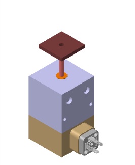
Remote Reset Device for Circuit Breakers
Our company's remote reset device controls the reset function of on-board circuit breakers via train transmission signals. This remote reset device for circuit breakers is a crucial vehicle safety device that enhances the safety and reliability of train operations, especially for fully automated driverless trains. When a short-circuit fault occurs and the circuit breaker cannot automatically close after resetting, the remote reset function ensures normal train operation and prevents service disruptions caused by circuit breaker issues.
Design Philosophy
To address the issue of manual reset impossibility in fully automated driverless trains and to ensure reliable and safe train operation, the design manipulates the circuit breaker reset device through the train's network control system. By connecting the remote reset module, remote control is achieved. The train's network control system is linked to the ground-based integrated monitoring system, enabling information transmission and command control between the train and the ground. This allows the ground control end to promptly send remote reset commands for circuit breakers.
Working Process
1. When a train fault occurs, the train's network control system collects the status of the circuit breaker through the remote input/output unit. The on-board or ground-based integrated monitoring system determines whether to send a remote reset command based on the collected status information.
2. If a reset is required, the ground-based integrated monitoring system sends a remote reset command for the circuit breaker. Upon receiving the command, the train's network control system outputs a remote reset DO pulse to drive the remote reset module.
3. After the remote reset module operates, the train's network control system judges whether the circuit breaker has successfully reclosed based on the status change of the circuit breaker's auxiliary contacts and feeds the result back to the ground-based integrated monitoring system.
4. If the circuit breaker still fails to close automatically after the fault reset, the ground-based integrated monitoring system will send another remote reset command for the circuit breaker, provided that the vehicle status is normal and no faults are detected.
5. If the ground-based integrated monitoring system determines that the vehicle status is abnormal, the system will switch to manual handling.
Quality Assurance
Our product uses the electromagnet module from Contrel, a supplier of Eaton products, to avoid all actions of lifting, dropping, and jamming caused by electromagnet failures. To prevent overheating due to prolonged electromagnet holding time, the product's working time has been optimized as much as possible. The working time is designed to be 100ms, ensuring full reset of the circuit breaker without interfering with its genuine automatic tripping function. To prevent misoperations caused by current noise, multiple filters have been added to the front end of the control chip circuit's field-effect transistor, thereby ensuring the stability of the product's signal input.
Technical Specifications | |
Control Voltage | 110V DC |
Signal Type | Pulse |
Control Current | 7.8mA (77VDC-137.5VDC) |
Operating Temperature | -40°C to 55°C |
Compliance Standards | EN 50155, IEC 61373, EN 45545 |
Lifespan | 10,000 cycles (2 times/minute) |
Dimensions | 35 x 57 x 35 mm |
Maximum Stroke | 20mm |
Mounting Plate Thickness | 2-5mm |
Weight | 305g |
Connection Method | Solenoid Valve Connector 4P |
Operating Voltage | 110V DC |
Operating Voltage Range | 77VDC-137.5VDC |
Operating Current | 0.93A @ 77VDC / 1.85A @ 137.5VDC |
Operating Time | 100ms |
Intelligent Train Control Board Set
Performance Description:
a) Data processing and fault diagnosis, event and fault identification and handling, data distribution, file processing;
b) Data storage;
c) Internal and external communication control;
d) System self-check.
Parameter Specification | |
Processor Frequency | ≥ 1.5GHz, AM5718AABPCA |
Memory | ≥ 1GB, 2 DDR3 chips |
Storage Card | 8GB eMMC (system disk), ≥32GB SATA (data disk), 16GB TF card (for debugging) |
Real-time Clock | IC interface integrated real-time clock circuit, provides calendar function for the system, and corrects time through the whole vehicle network system time. Model: DS1337S+ |
Ethernet Interface | Built-in port 0: Backplane data network (upper header); Built-in port 1: Front panel M12; Built-in USB port (USB2.0): Backplane service network (lower header), LAN9500AI |
CAN Interface | 1 CAN2.0B (using built-in CAN1), used for backplane CAN communication; ISO1050 transceiver, single board does not terminate |
RS485 Interface | 1 RS485 for backplane communication (UART2), DE uses C28 ISO3082 transceiver, single board does not terminate |
Serial Port | 1 debugging serial port, 1 RS232 used for debugging interface (UART1, 3-GND, 2-RX, 1-TX) |
Rear Panel DO | 1 DO: > 100mA, 24V, relay output high level is valid, outputs 24V with a distance of 5.08 for the two-core connector |
Operating System | QNX: 7.0 |
Carriage Number Setting | Uses DIP switch setting, BCD code, 1 is valid, brand: OMRON, model: A6A-16C; 1 DIP switch is reserved, DIP switches are arranged in parallel at the bottom left of the board, with loose space adjustment, and统一 (unified) use of Chinese characters for silkscreen printing |
Power Supply | Dual DC24V isolated power supply design, the total power consumption of the board is less than 9W; each power input end needs to be protected by a fast-blow fuse, the fuse parameter should be 1.5 to 2 times the actual working current; in case of overcurrent/short circuit of the single board power supply, it should disconnect the input power supply in time to isolate the internal and external circuits. The power supply output side of the power module uses a parallel common ground scheme (diode model: STPS3045DJF); power supply voltage monitoring: 4.5-5.5V is high level, others are low level |
Operating Temperature | -40℃ to +70℃, all components are industrial grade |
PCB | Board thickness 1.8mm |

160 km/h Passenger Train Alarm Display Terminal
Performance Description:
The alarm display terminal is designed and developed based on the TI OMAP-L138 floating-point DSP+ARM dual-core processor, equipped with a 7-inch LCD screen and a resistive touch screen as an integrated human-machine interaction terminal. This terminal interacts with the target device through communication interfaces, and in conjunction with corresponding application software according to actual business needs, it can provide alarm information on the status of the target device and achieve centralized display and configuration.
Technical Specifications | |
Panel Size | 7-inch (G070VW01) |
Resolution | 800*480 |
Brightness | 300 nits |
Contrast Ratio | Minimum 700 |
Backlight | Lifespan 30,000 hours |
Buzzer | Configurable buzzer |
Touch Screen | 4-wire high-precision resistive, hardness > 3H, 1 million single touches |
Communication Interface | 1 USB, 1 Ethernet, 2 RS232 |
Processor | TI OMAPL138, specific model OMAPL138EZWTD4, main frequency 456MHz |
FLASH | K9F4G08U0E-SIBO0 not less than 128MB |
RAM | MT47H32M16HR-25E-IT:G 64MB |
Operating System | QNX Neutrino 6.4.0 |

Locomotive Fire Monitoring Subsystem
Performance Description:
This subsystem detects smoke, heat, and other physical quantities through various sensors such as smoke detectors, temperature detectors, and thermal cables installed in the driver's cabin, mechanical compartment, electrical compartment, power supply cabinet, diesel engine room (for diesel locomotives), etc., to monitor whether a fire has occurred and issue timely alarms. All detection and alarm devices can signal alarms or fault indicators through local indicator lights. In the event of a fire, it can link with the video monitoring system to automatically switch the video display to the fire location while indicating the fire alarm.
Technical Specifications | |
Board Power Supply Requirements | |
Fire Monitoring Board Rated Voltage | DC24V ± 25% |
Rated Power | < 25W |
CAN Bus Interface | Communicates with the central processing platform |
Detector Interface | Communicates with fire monitoring detectors and fire extinguishing (optional) controllers over the network. Sends data once every second during an alarm, and sends board status data once every 10 seconds when no alarm is present. The SD card can store relevant data of the fire protection subsystem in real-time. The serial port can output real-time data from the detector. The board itself has the capability for fault self-check and self-check of detector network faults, and sends the self-check results to the central processing platform. |
Smoke Detector | |
Parameter | Description |
Operating Voltage | 15 ~ 32VDC |
Quiescent Current | ≤ 350μA (at 24VDC) |
Alarm Current | ≤ 3.5mA |
Ambient Temperature | -40°C ~ 70°C |
Dimensions | Diameter × Height = 102mm × 42mm |
Thermal Detector Usage Parameters | |
Parameter | Description |
Fixed Temperature Alarm Temperature | 90°C |
Operating Voltage | 15 ~ 32VDC |
Ambient Temperature | -40°C ~ 70°C |
Dimensions | Diameter × Height = 102mm × 42mm |
Thermal Cable Composition | |
Parameter | Description |
Alarm Temperature | 180°C ± 5°C |
Over-temperature Alarm Response Time | ≤ 20 seconds |
Protection Level | IP65 |
Installation Method | Fixed using four holes on the box itself, with M4X20 bolts, each terminal box is equipped with 4 bolts and corresponding spring washers |
Thermal Cable Terminal Box | Same as above |
Thermal Cable Intermediate Box | Same as above |
Input Module, Electronic Encoding Method | |
Parameter | Description |
Operating Voltage | 15 ~ 32VDC |
Ambient Temperature | -40°C ~ 70°C |
Dimensions | Length × Width × Thickness = 86mm × 86mm × 34mm |

Locomotive Automatic Monitoring Video and Recording Subsystem
Performance Description:
This subsystem allows the driver to promptly understand the conditions both inside and outside the locomotive by installing cameras in various locations such as the driver's cabin and mechanical compartments, and records the operating status of the locomotive. By linking with the fire monitoring subsystem, this subsystem can automatically switch to the video image of the area where a fire occurs when a fire happens.
Technical Specifications | ||
| Main Function | Audio and video signal acquisition, conversion, digitization, compression, and encoding, etc. |
Rated Voltage | DC 24V | |
Rated Power | < 25W | |
Video Channel Quantity | 7 channels | |
Audio Channel Quantity | 1 channel | |
Communication Interface | Ethernet | |
Audio and Video Data Rate | Real-time transmission of audio and video, communication bandwidth < 20 Mbps | |
Video Encoding Capability | Not less than 25 fps | |
Video Encoding Resolution | All channels support CIF, 2CIF or D1CF, 4CIF formats | |
Video Bit Width | ≥ 8 bit | |
Audio and Video Acquisition Card 2 | Main Function | Includes audio and video data storage, audio and video data download, system parameter configuration, etc. |
Rated Voltage | DC 24V | |
Rated Power | < 25W | |
Communication Interface | Ethernet | |
USB Data Download Interface | USB3.0 | |
Audio and Video Data Rate | Real-time transmission of audio and video, communication bandwidth < 20 Mbps | |
Audio and Video Storage Time | ≥ 15 days | |
Audio and Video Storage Hard Disk | The audio and video storage hard disk should use an industrial-grade solid-state hard disk with storage media of MLC or higher. The hard disk technical parameters should comply with the unified requirements of the 6A system ground processing system: SATA2 interface, storage capacity not less than 500 GB, and the partition format should use FAT32. | |
| Type | Omnidirectional |
Rated Voltage | DC 12V | |
Signal-to-Noise Ratio | ≥ 50 dB | |
Sensitivity | Less than -38 dB | |
Housing Requirement | Metal | |
Camera | Parameter | Road Condition Camera |
Type | Color camera | |
Rated Voltage | DC 12V | |
Rated Power | ≤ 5 W (without heating), ≤ 20 W (with heating) | |
Horizontal Resolution (Standard) | ≥ 700 TV lines, actual measurement error not greater than 10% | |
Signal-to-Noise Ratio | ≥ 48 dB | |
Lens Focal Length | 12 mm | |
Lens Aperture | F1.4 | |
Low Light Level | 0.5 LUX can work normally | |
Housing Requirement | Metal | |
Camera Lens Surface Treatment | Tempered glass | |
Camera Housing Surface Treatment | Spray paint | |
Camera Housing Color | RAL 9004 (Custom processing if special requirements from the user) | |
Protection Level | IP65 (indoor) | |
Parameter | Driver's Cabin Camera | |
Type | Infrared color camera, infrared light automatically turns on and off | |
Rated Voltage | DC 12V | |
Rated Power | ≤ 5 W (without heating), infrared supplementary light power 3 W± 0.45 W | |
Horizontal Resolution (Standard) | ≥ 700 TV lines, actual measurement error not greater than 10% | |
Signal-to-Noise Ratio | ≥ 48 dB | |
Lens Focal Length | 2.8 mm | |
Lens Aperture | F1.8 | |
Low Light Level | 0 LUX can work normally, less than 10 LUX turns black and white | |
Housing Requirement | Metal | |
Camera Lens Protection Material | Tempered glass | |
Camera Lens Surface Treatment | Spray paint | |
Camera Housing Color | RAL 9004 (Custom processing if special requirements from the user) | |
Protection Level | IP65 | |
Parameter | Mechanical Compartment Camera | |
Type | Infrared color camera, infrared light automatically turns on and off | |
Rated Voltage | DC 12V | |
Rated Power | ≤ 5W (without heating, infrared supplementary light power 3W± 0.45W) | |
Horizontal Resolution (Standard) | ≥ 700 TV Lines, actual measurement error not greater than 10% | |
Signal-to-Noise Ratio | ≥ 48 dB | |
Lens Focal Length | 3.6 mm | |
Lens Aperture | F1.8 | |
Low Light Level | 0 LUX can work normally, less than 10 LUX turns black and white | |
Housing Requirement | Metal | |
Camera Lens Protection Material | Tempered glass | |
Camera Housing Surface Treatment | Spray paint | |
Camera Housing Color | RAL 9004 (Custom processing if there are special requirements from the user) | |
Protection Level | IP65 (indoor) | |

DC-110 Onboard Leakage Alarm
Performance Description:
The DC110V online insulation monitoring system mainly consists of train-level insulation monitoring, vehicle-level insulation monitoring, midpoint resistance, and communication network. The train-level insulation monitoring is composed of the DC110V leakage alarm, head and tail vehicle bus voltage and ground voltage sensors. The vehicle-level insulation monitoring is composed of leakage current sensors and conditioning modules. The midpoint resistance is composed of DC110V line-to-line resistance and ground resistance. The onboard leakage alarm detects leakage in the circuit through a current sensor. When a leakage current exceeding the preset threshold is detected, the alarm will issue an alert signal to remind the driver or maintenance personnel to deal with it in time to avoid safety accidents caused by leakage.
Technical Specifications | |
Ambient Temperature | -40°C to 45°C |
Altitude | Not exceeding 2500m |
Relative Humidity | Monthly average maximum relative humidity not greater than 95% (when the monthly average minimum temperature is 25°C) |
Shock and Vibration | Should comply with the relevant provisions of Class B, Grade 1 of CB/T21563-2008 |
Operating Environment | Wind, sand, rain, snow weather, occasional salt fog, acid rain, dust storms, etc. Special circumstances may have long-term continuous salt fog phenomena. |
Lifespan | The designed service life should not be less than 12 years |
Dimensions | 144mm × 83mm × 47 mm |
Enclosure Protection Level | IP30 |
Weight | The weight of the leakage alarm device should not exceed 1KG |
Power and Communication Interface | 2EDGRM-3.81-11P, for device power supply and alarm information upload |
Power Supply Voltage | The power supply voltage for the leakage alarm device is DC24V (DC16.8V~DC30V) |
Alarm Threshold | Leakage alarm value: when the line-to-ground voltage/output voltage is less than 25%, it is determined as positive leakage, and when it is greater than 70%, it is determined as negative leakage |
PCB | Board thickness 1.6 mm |
Processor | STM32F103C8T6 32-bit microcontroller, program memory capacity is 64KB, requires voltage 2V~3.6V, operating temperature range is -40°C to 85°C |
Function Description | 1. Self-check function |
2. Positive pole line leakage alarm | |
3. Negative pole line leakage alarm | |
4. Alarm self-reset | |
5. Test function | |
6. Mute function | |
7. Alarm data recording | |
8. Power polarity reverse protection | |

Tire Pressure Monitoring System (TPMS)
Performance Description:
The system is an essential component of the real-time online monitoring system for monorail rubber-tired trains, providing significant support for the safe operation of monorail trains. The sensors of the tire pressure monitoring transmit real-time tire pressure data to the receiver via wireless communication protocols. At the same time, the receiver transmits the data to the TPMS host through the 485 bus. The host decodes and analyzes the received data, uploads it to the TCMS network, and issues corresponding alarm signals for different working conditions.
Technical Specifications | ||
Operating Conditions | Operating Speed | 80 km/h |
Storage Temperature | -40°C to 70°C | |
Ambient Temperature | -25°C to 40°C | |
Annual Average Relative Humidity | 0.9 | |
Altitude | ≤ 1200 m | |
Communication Method | Host and TCMS | Host and TCMS; CAN OPEN |
Receiver and Host | Receiver and Host; RS485 | |
Sensor and Receiver | Sensor and Receiver; 433.92MHz | |
RJ45 Interface | Used for debugging and software program upgrade | |
IP Rating | Sensor IP65; Host IP54; Receiver IP65 | |
Alarm Definition | Trigger Condition | Alarm Information |
Travel Tire Pressure < 10.5 bar | Triggers "Travel Tire Pressure Too Low" alarm information | |
Travel Tire Pressure < 11.0 bar | Triggers "Travel Tire Pressure Low" alarm information | |
Travel Tire Pressure > 14.1 bar | Triggers "Travel Tire Pressure Too High" alarm information | |
Guidance Tire Pressure < 9.0 bar | Triggers "Guidance Tire Pressure Too Low" alarm information | |
Guidance Tire Pressure < 9.5 bar | Triggers "Guidance Tire Pressure Low" alarm information | |
Guidance Tire Pressure > 13.0 bar | Triggers "Guidance Tire Pressure Too High" alarm information | |
Sensor High Line Exceeds 5 Minutes | Triggers "Sensor Fault" alarm information | |
Battery Voltage Below 2.4V DC | Triggers "Battery Voltage Too Low" alarm informatio | |

Online Insulation Monitoring Device
Performance Description:
The online insulation monitoring device is composed of a host, current transformer (current ratio device), test resistor, test button, power connector, and related wiring. The device can monitor the system's insulation resistance to ground in real-time, including the insulation status of single-phase or multi-phase systems. When the insulation resistance falls below a preset threshold or a ground fault is detected, it issues an alarm signal through indicator lights, buzzers, or communication interfaces to alert operators to address the issue promptly.
Technical Specifications | |||
Operating Conditions | Ambient Temperature | -40°C to 45°C | |
Altitude | Not exceeding 2500 m | ||
Relative Humidity | Monthly average maximum relative humidity not greater than 95% (when the monthly average minimum temperature is 25°C) | ||
Operating Environment | Wind, sand, rain, snow, occasional salt mist, acid rain, dust storms, etc. Special circumstances may have long-term continuous salt mist phenomena | ||
Grounding Method | Using separate neutral and ground wires | ||
Lifespan | Under normal use, maintenance, and preservation conditions, the design service life should not be less than 12 years. | ||
Housing Material and Thickness | Metal plate or PC material, thickness greater than 1.0mm | ||
Buzzer | Alarm sound pressure level should reach 70dB ± 5dB (A) | ||
Weight | The weight of the device should not exceed 1.5 kg | ||
Power Interface | FKCVR2.5/9-ST-5.08(PHOENIX) | ||
Power Supply Voltage | AC220V (AC187V ~ 253V/50Hz) Power consumption < 10W | ||
Leakage Current Threshold | 150mA±5mA | ||
Output Control Contact Capacity | 5A 240VAC/5A 28VDC | ||
Output Control Contact Number | One normally open and one normally closed contact (common terminal) | ||
Functional Requirements | 1.When the leakage current of the electrical load insulation exceeds 150 mA (±5mA), an alarm is triggered (action time less than 1 second), the alarm light comes on and the buzzer sounds, while also providing a relay output control signal and self-locking. | ||

 苏公网安备32010602012177号